ESP32快速参考
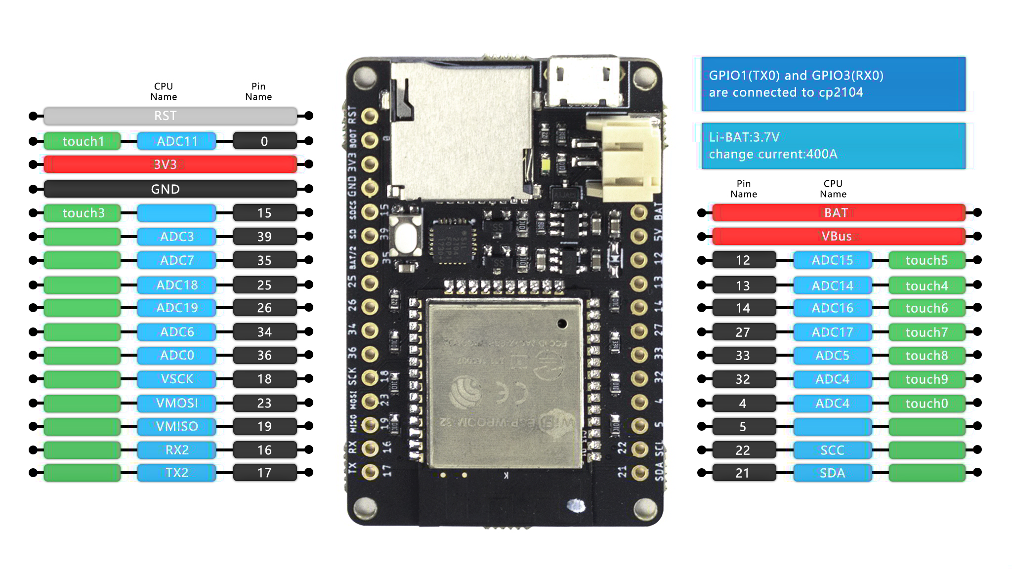
The SingTown ESP32 board (image attribution: SingTown).
安装 MicroPython
详见教程的相关章节: Getting started with MicroPython on the ESP8266. 它也包括一个疑难问题的解答。
通用硬件控制
MicroPython REPL 在 UART0 (GPIO1=TX, GPIO3=RX) 上,波特率为 115200。 Tab自动补全很有用,尤其是想找到一个对象有什么方法的时候。 粘贴模式 (ctrl-E) 也很有用,当你粘贴一大段python代码的时候。
详见 machine.
import machine

machine.freq()          # get the current frequency of the CPU
machine.freq(160000000) # set the CPU frequency to 160 MHz
注意: machine.freq(16000000) 功能还没有实现
详见 esp:
import esp

esp.osdebug(None)       # turn off vendor O/S debugging messages
esp.osdebug(0)          # redirect vendor O/S debugging messages to UART(0)
网络
详见 network:
import network

wlan = network.WLAN(network.STA_IF) # create station interface
wlan.active(True)       # activate the interface
wlan.scan()             # scan for access points
wlan.isconnected()      # check if the station is connected to an AP
wlan.connect('essid', 'password') # connect to an AP
wlan.config('mac')      # get the interface's MAC adddress
wlan.ifconfig()         # get the interface's IP/netmask/gw/DNS addresses

ap = network.WLAN(network.AP_IF) # create access-point interface
ap.active(True)         # activate the interface
ap.config(essid='ESP-AP') # set the ESSID of the access point
下面的函数在连接Wi-Fi网络的时候很有用:
def do_connect():
    import network
    wlan = network.WLAN(network.STA_IF)
    wlan.active(True)
    if not wlan.isconnected():
        print('connecting to network...')
        wlan.connect('essid', 'password')
        while not wlan.isconnected():
            pass
    print('network config:', wlan.ifconfig())
一旦网络建立, 你就可以用熟悉的 socket 来创建和使用TCP/UDP sockets。
延时和时间
详见 time:
import time

time.sleep(1)           # sleep for 1 second
time.sleep_ms(500)      # sleep for 500 milliseconds
time.sleep_us(10)       # sleep for 10 microseconds
start = time.ticks_ms() # get millisecond counter
delta = time.ticks_diff(time.ticks_ms(), start) # compute time difference
定时器
支持虚拟的 (基于RTOS) 的定时器。 timer ID 为 -1:
from machine import Timer

tim = Timer(-1)
tim.init(period=5000, mode=Timer.ONE_SHOT, callback=lambda t:print(1))
tim.init(period=2000, mode=Timer.PERIODIC, callback=lambda t:print(2))
period 的单位是毫秒,period为定时时间,每经过这段时间就会执行callback函数。
引脚和GPIO
详见 machine.Pin:
from machine import Pin

p4 = Pin(4, Pin.OUT)    # create output pin on GPIO4
p4.value(0)             # set pin to high level
p4.value(1)             # set pin to low level

p5 = Pin(5, Pin.IN)     # create input pin on GPIO2
print(p5.value())       # get value, 0 or 1

p4 = Pin(4, Pin.IN, Pin.PULL_UP) # enable internal pull-up resistor
p5 = Pin(5, Pin.OUT, value=1) # set pin high on creation
可供使用的引脚有: 0, 2, 4, 5, 12, 13, 14, 15, 16, 17, 18, 19, 21, 22, 23, 25, 26, 27, 32, 33, 34, 35, 36,39. 它们是芯片实际GPIO的引脚标号。注意很多开发板使用他们自己的特殊编号(比如D0, D1, …)
因为MicroPython支持许多的板子和模组,使用物理的引脚编号是因为它们是最通用的编号。 为了对应你的板子的逻辑引脚和物理芯片上的引脚,参考你的板子的文档。
注意: GPIO0 和 GPIO2 是 strapping pin, 它们可能会影响启动. GPIO1 和 GPIO3 是 REPL串口 TX RX 引脚. GPIO6-11 一般连接到 SPI flash. GPIO34-39 只能被设置为输入模式,并且软件没有上拉/下拉功能。
PWM (pulse width modulation)
PWM 可以在所有的输出引脚上使用。ESP32有8个PWM通道,它们使用同一个频率(范围1~78125HZ)。 占空比在0~1023之间。
详见 machine.PWM:
from machine import Pin, PWM

pwm4 = PWM(Pin(4))      # create PWM object from a pin
pwm4.freq()             # get current frequency
pwm4.freq(1000)         # set frequency
pwm4.duty()             # get current duty cycle
pwm4.duty(200)          # set duty cycle
pwm4.deinit()           # turn off PWM on the pin

pwm5 = PWM(Pin(5), freq=5000, duty=512) # create and configure in one go
注意: GPIO0 和 GPIO2 是 strapping pin, 它们可能会影响启动. GPIO1 和 GPIO3 是 REPL串口 TX RX 引脚. GPIO6-11 一般连接到 SPI flash. GPIO34-39 只能被设置为输入模式,并且软件没有上拉/下拉功能。
ADC (模数转换)
详见 machine.ADC:
from machine import Pin, ADC

adc = ADC(Pin(35))            # create ADC object on ADC pin
adc.read()                    # read value, 0-4095s
注意:
ADC 在引脚 32~39 上可用。
GPIO37-38 一般连接到一个电容,用于 ADC_PRE_AMP。
ADC 引脚的输入电压在0v 到 1.1v之间。
UART (通用异步收发器)串口
ESP32芯片上,有3个 UART控制器。
详见 machine.UART
| Pin | rx | tx |
|---|---|---|
| UART0 | 3 | 1 |
| UART1 | 23 | 19 |
| UART2 | 5 | 18 |
注意: UART0 已经被 REPL 使用。
from machine import Pin, UART
uart1 = UART(1, 115200) uart1.any() uart1.write(‘hello world!’) uart1.read(1)
软件 SPI 总线
有两个SPI驱动,一个是软件实现的(bit-banging),可以用于任何引脚。
详见 machine.SPI:
from machine import Pin, SPI

# construct an SPI bus on the given pins
# polarity is the idle state of SCK
# phase=0 means sample on the first edge of SCK, phase=1 means the second
spi = SPI(-1, baudrate=100000, polarity=1, phase=0, sck=Pin(0), mosi=Pin(4), miso=Pin(5))

spi.init(baudrate=200000) # set the baudrate

spi.read(10)            # read 10 bytes on MISO
spi.read(10, 0xff)      # read 10 bytes while outputing 0xff on MOSI

buf = bytearray(50)     # create a buffer
spi.readinto(buf)       # read into the given buffer (reads 50 bytes in this case)
spi.readinto(buf, 0xff) # read into the given buffer and output 0xff on MOSI

spi.write(b'12345')     # write 5 bytes on MOSI

buf = bytearray(4)      # create a buffer
spi.write_readinto(b'1234', buf) # write to MOSI and read from MISO into the buffer
spi.write_readinto(buf, buf) # write buf to MOSI and read MISO back into buf
硬件 SPI 总线
硬件的 SPI 更快 (高达80Mhz),因为esp32的GPIO Matrix功能,你可以在任意的引脚绑定。
Native SPI pins:
| SPI | id | clk | mosi | miso |
|---|---|---|---|---|
| HSPI | 1 | 14 | 13 | 12 |
| VSPI | 2 | 18 | 23 | 19 |
Native pins 最大的 SPI 时钟可以到达 80 MHZ. 如果你使用了 gpio matrix 连接到其他的引脚, 最大 spi 时钟是 40 MHz(半双工),26 MHz(全双工) 所以,大多数情况下(当你不需要大于26MHZ的速度),miso你可以使用任意的引脚,mosi, clk & cs使用任意的输入输出引脚。
注意:
因为 DMA 冲突,你只能同时使用一个spi总线,但是一个spi总线可以连接很多设备,使用不同的cs引脚。 他和上面的软件SPI驱动有相同的方法,除了引脚参数和编号:
from machine import Pin, SPI

hspi = SPI(1, sck=Pin(14), mosi=Pin(13), miso=Pin(12), baudrate=80000000)
vspi = SPI(2, sck=Pin(18), mosi=Pin(23), miso=Pin(19), baudrate=80000000)

#or any pin with up 24MHZ

hspi = SPI(1, sck=Pin(5), mosi=Pin(4), miso=Pin(6), baudrate=24000000)
vspi = SPI(2, sck=Pin(12), mosi=Pin(13), miso=Pin(14), baudrate=10000000)
I2C bus
I2C驱动是软件实现的,并且在所有的引脚上都可以使用。
详见 machine.I2C:
from machine import Pin, I2C

# construct an I2C bus
i2c = I2C(scl=Pin(22), sda=Pin(21), freq=100000)
print(i2c.scan())
i2c.readfrom(0x3a, 4)   # read 4 bytes from slave device with address 0x3a
i2c.writeto(0x3a, '12') # write '12' to slave device with address 0x3a

buf = bytearray(10)     # create a buffer with 10 bytes
i2c.writeto(0x3a, buf)  # write the given buffer to the slave
实时时钟 (RTC)
注意: RTC 还没有实现
详见 machine.RTC
from machine import RTC

rtc = RTC()
rtc.datetime((2017, 8, 23, 1, 12, 48, 0, 0)) # set a specific date and time
rtc.datetime() # get date and time
Deep-sleep mode
注意: Deep-sleep mode has not been achieved.
Connect GPIO16 to the reset pin (RST on HUZZAH). Then the following code can be used to sleep, wake and check the reset cause:
import machine

# configure RTC.ALARM0 to be able to wake the device
rtc = machine.RTC()
rtc.irq(trigger=rtc.ALARM0, wake=machine.DEEPSLEEP)

# check if the device woke from a deep sleep
if machine.reset_cause() == machine.DEEPSLEEP_RESET:
    print('woke from a deep sleep')

# set RTC.ALARM0 to fire after 10 seconds (waking the device)
rtc.alarm(rtc.ALARM0, 10000)

# put the device to sleep
machine.deepsleep()
OneWire 驱动
OneWire 驱动是软件实现的,并且在所有的引脚上都可以使用:
from machine import Pin
import onewire

ow = onewire.OneWire(Pin(12)) # create a OneWire bus on GPIO12
ow.scan()               # return a list of devices on the bus
ow.reset()              # reset the bus
ow.readbyte()           # read a byte
ow.writebyte(0x12)      # write a byte on the bus
ow.write('123')         # write bytes on the bus
ow.select_rom(b'12345678') # select a specific device by its ROM code
这是一个DS18S20和DS18B20的专门的驱动。
import time, ds18x20 ds = ds18x20.DS18X20(ow) roms = ds.scan() ds.convert_temp() time.sleep_ms(750) for rom in roms:
print(ds.read_temp(rom))
请确定一个4.7k的上拉电阻连接在信号线。注意 convert_temp() 方法一定在你想测量温度的时候调用。
NeoPixel 驱动
详见 :ref:
neopixelmodule:from machine import Pin from neopixel import NeoPixel pin = Pin(4, Pin.OUT) # set GPIO4 to output to drive NeoPixels np = NeoPixel(pin, 8) # create NeoPixel driver on GPIO4 for 8 pixels np[0] = (255, 255, 255) # set the first pixel to white np.write() # write data to all pixels r, g, b = np[0] # get first pixel colour
NeoPixel还有一个底层的驱动:
import esp
esp.neopixel_write(pin, grb_buf, is800khz)
TouchPad 驱动
ESP32提供了10个电容触摸引脚。它们分别是: 0, 2, 4, 12, 13, 14, 15, 27, 32, 33 当用户触摸表面,电容的变化会触发,一个信号的值会返回。
详见 TouchPad:
from machine import Pin, TouchPad

tc = TouchPad(Pin(4))   # create TouchPad driver on GPIO4
tc.read()               # when touch the pad, the value will low around 80;
                        # if float ,the value is around 1000
APA102 driver
注意: APA102 驱动还没有实现
详见 the apa102 module:
from machine import Pin
from apa102 import APA102

clock = Pin(14, Pin.OUT)     # set GPIO14 to output to drive the clock
data = Pin(13, Pin.OUT)      # set GPIO13 to output to drive the data
apa = APA102(clock, data, 8) # create APA102 driver on the clock and the data pin for 8 pixels
apa[0] = (255, 255, 255, 31) # set the first pixel to white with a maximum brightness of 31
apa.write()                  # write data to all pixels
r, g, b, brightness = apa[0] # get first pixel colour
For low-level driving of an APA102:
import esp
esp.apa102_write(clock_pin, data_pin, rgbi_buf)
DHT 驱动
DHT驱动是软件实现的,并且工作在所有的引脚。
import dht import machine
d = dht.DHT11(machine.Pin(4)) d.measure() d.temperature() # eg. 23 (°C) d.humidity() # eg. 41 (% RH)
d = dht.DHT22(machine.Pin(4)) d.measure() d.temperature() # eg. 23.6 (°C) d.humidity() # eg. 41.3 (% RH)
WebREPL (web browser interactive prompt)
WebREPL (WebSockets的REPL, 可通过网络浏览器访问) 是在ESP32可用的实验性质的功能。 下载网页客户端https://github.com/micropython/webrepl (主机版本可在以下地址获得:http://micropython.org/webrepl),并通过执行下列命令对其进行配置:
import webrepl_setup
并遵循屏幕上的指令。重启后,连接即可用。若您在启动时禁用自动启动,那么您可根据需要运行配置的守护进程:
import webrepl webrepl.start()
您可通过连接ESP32的热点来使用WebREPL,但守护进程也会在STA接口上启动(如果启动), 所以若您的路由器设置正确且工作正常,您可能也会在连接到正常网络接入点时使用WebREPL( 若您遇到任何问题,请使用ESP32 AP连接方法)。
除终端/命令提示访问外,WebREPL也提供文件传递(包括上传和下载)。 网页客户端有对应函数的按钮,您也可以从上述存储库中使用命令行客户端
其他社区支持的传输文件到ESP32的替代方案,请参见MicroPython论坛。