openmvcam快速参考
以下是OpenMV Cam的快速参考。如果这是您第一次使用OpenMV Cam,请先阅读以下部分:
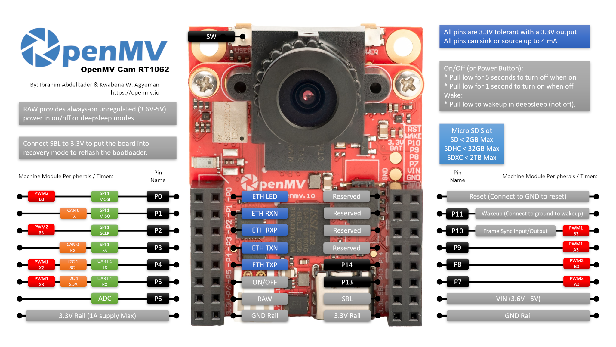
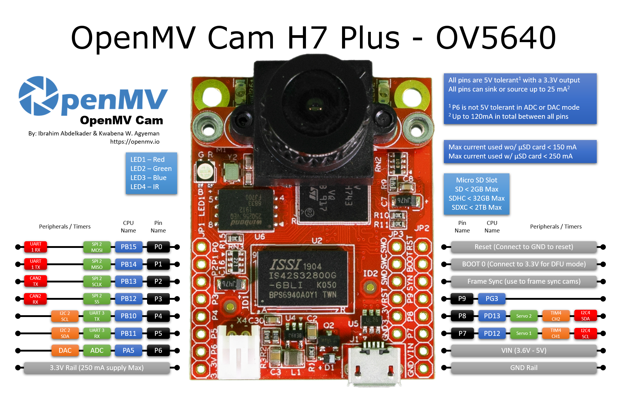
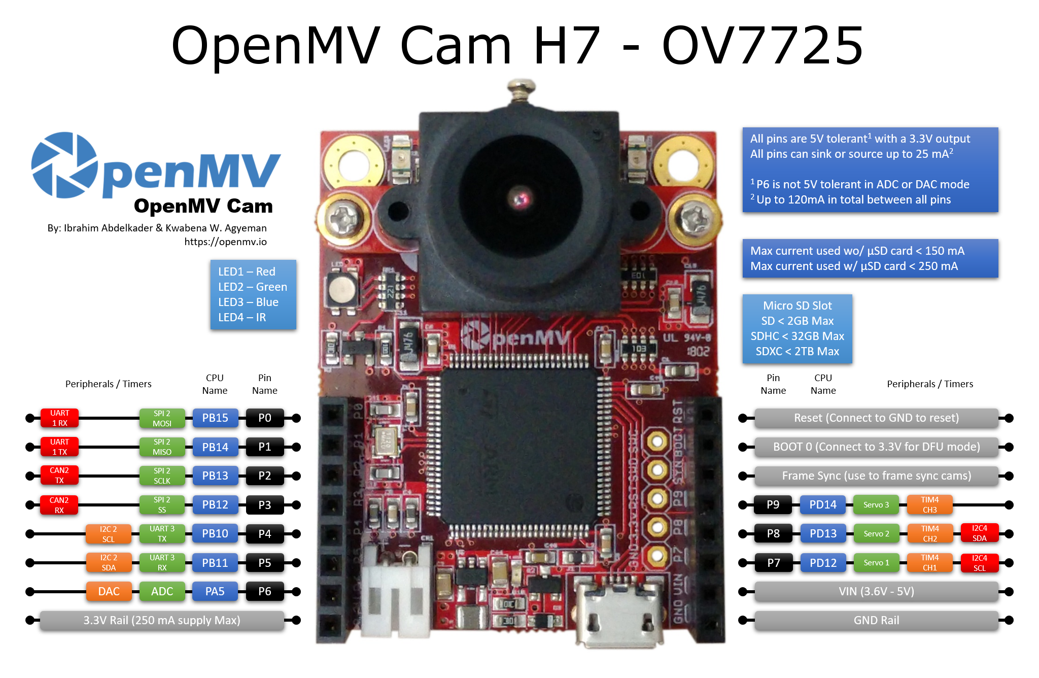
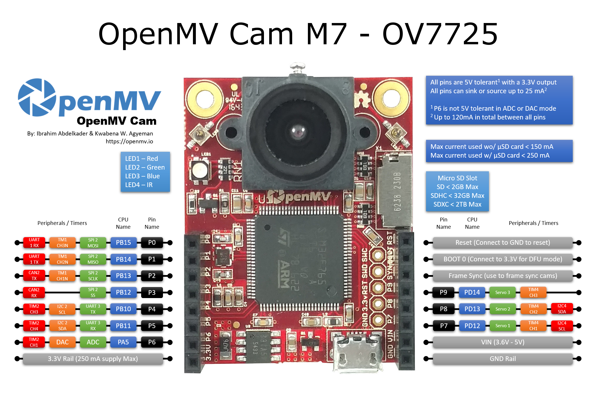
通用OpenMV Cam板控制
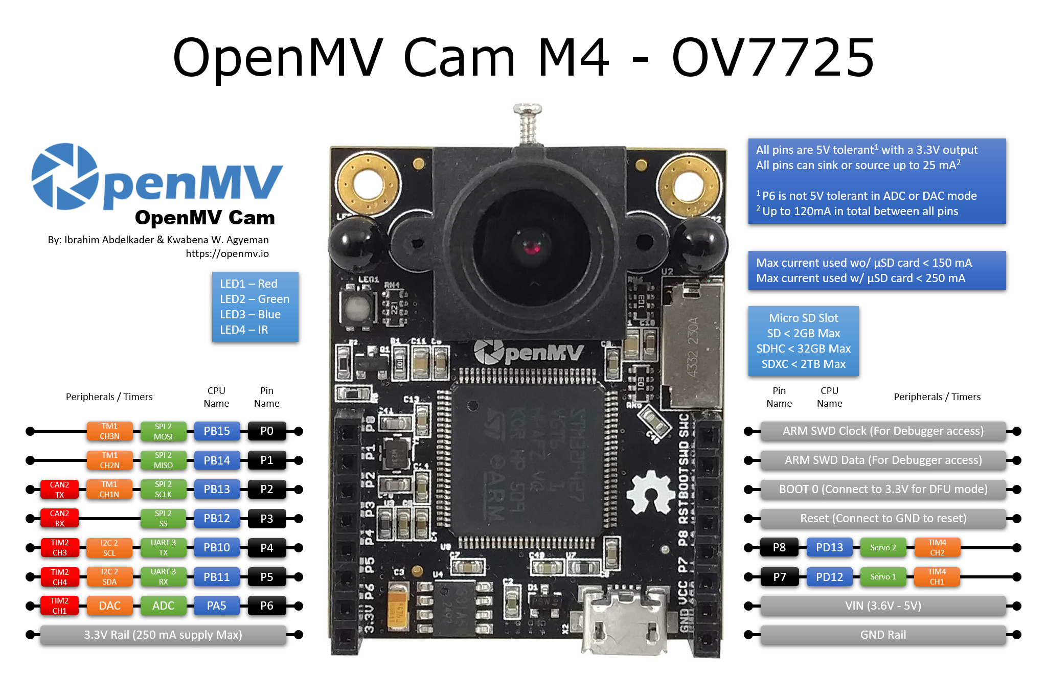
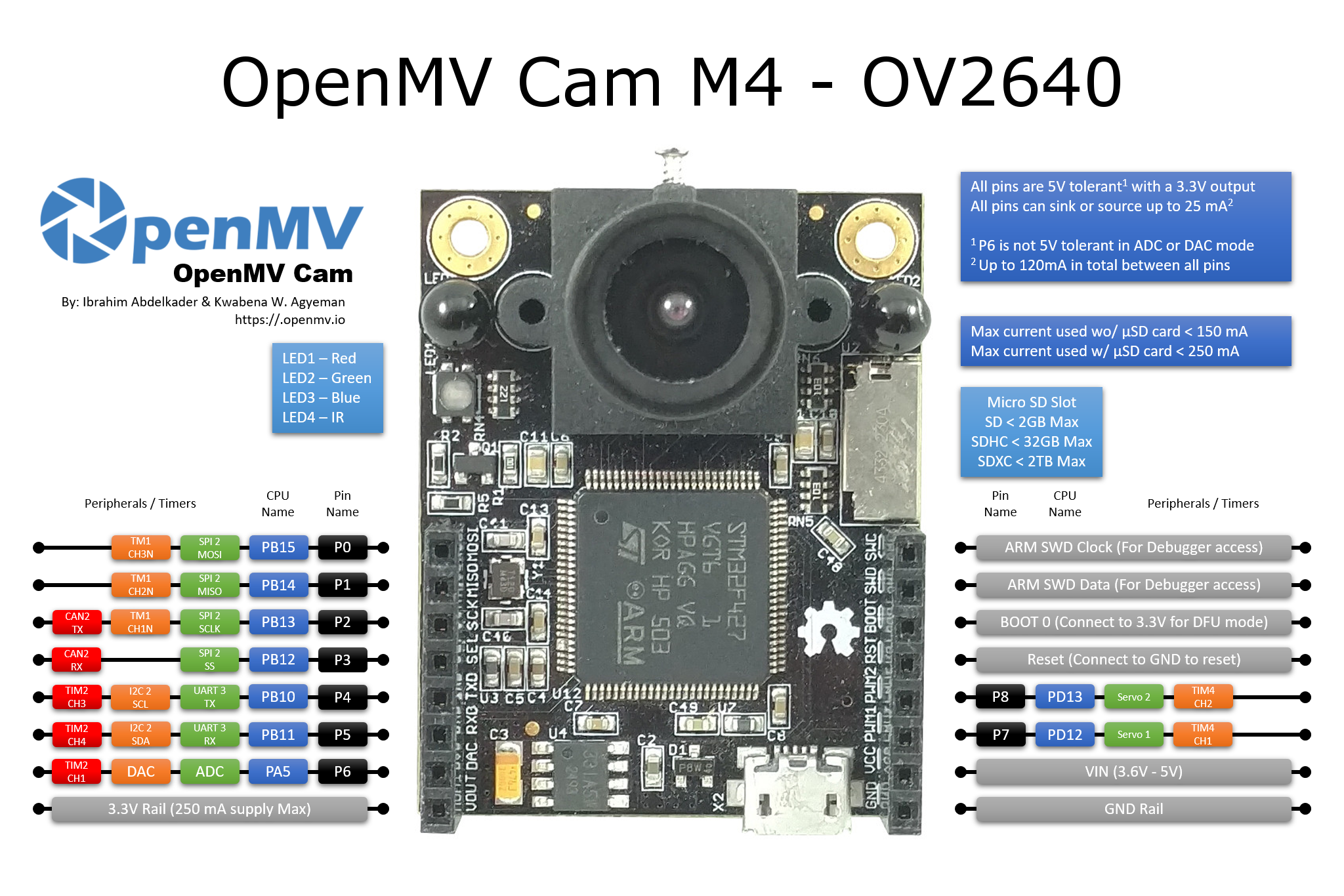
所有 OpenMV 摄像头都可以使用 machine 模块来控制相机硬件。请参考引脚图,以了解哪些 SPI/I2C/UART/CAN/PWM/TIMER 通道可用以及它们对应的 I/O 引脚。
延时和时间
使用 time 模块:
import time

time.sleep(1)           # sleep for 1 second
time.sleep_ms(500)      # sleep for 500 milliseconds
time.sleep_us(10)       # sleep for 10 microseconds
start = time.ticks_ms() # get millisecond counter
delta = time.ticks_diff(time.ticks_ms(), start) # compute time difference
虚拟定时器
用法示例:
from machine import Timer

tim0 = Timer(-1)
tim0.init(period=5000, mode=Timer.ONE_SHOT, callback=lambda t:print(0))

tim1 = Timer(-1)
tim1.init(period=2000, mode=Timer.PERIODIC, callback=lambda t:print(1))
周期以毫秒为单位。
引脚和GPIO
使用 machine.Pin 类:
from machine import Pin

p0 = Pin('P0', Pin.OUT) # create output pin on GPIO0
p0.on()                 # set pin to "on" (high) level
p0.off()                # set pin to "off" (low) level
p0.value(1)             # set pin to on/high

p2 = Pin('P2', Pin.IN)  # create input pin on GPIO2
print(p2.value())       # get value, 0 or 1

p4 = Pin('P4', Pin.IN, Pin.PULL_UP) # enable internal pull-up resistor
p5 = Pin('P5', Pin.OUT, value=1) # set pin high on creation
还有一个更高级的抽象 machine.Signal ,可用于反转引脚。 用于使用 on() 或 value(1) 点亮低电平激活的LED非常有用。
UART(串行总线)
参见 machine.UART。:
from machine import UART

uart1 = UART(1, baudrate=115200)
uart1.write('hello')  # write 5 bytes
uart1.read(5)         # read up to 5 bytes
PWM(脉冲宽度调制)
PWM功能由 machine.PWM 类提供。它支持该类列出的所有基本方法以及一些额外方法来处理信号组。
from machine import Pin, PWM

pwm2 = PWM("P6")      # create PWM object from a pin
pwm2.freq()             # get current frequency
pwm2.freq(1000)         # set frequency
pwm2.duty_u16()         # get current duty cycle, range 0-65535
pwm2.duty_u16(200)      # set duty cycle, range 0-65535
pwm2.deinit()           # turn off PWM on the pin
# create a complementary signal pair on Pin 2 and 3
pwm2 = PWM((6, 7), freq=2000, duty_ns=20000)

# Create a group of four synchronized signals.
# Start with Pin(4) at submodule 0, which creates the sync pulse.
pwm4 = PWM(Pin(4), freq=1000, align=PWM.HEAD)
# Pins 5, 6, and 9 are pins at the same module
pwm5 = PWM(Pin(5), freq=1000, duty_u16=10000, align=PWM.HEAD, sync=True)
pwm6 = PWM(Pin(6), freq=1000, duty_u16=20000, align=PWM.HEAD, sync=True)
pwm9 = PWM(Pin(9), freq=1000, duty_u16=30000, align=PWM.HEAD, sync=True)

pwm3                    # show the PWM objects properties
ADC(模数转换)
使用 machine.ADC 类:
from machine import ADC

adc = ADC("P5")          # create ADC object on ADC pin
adc.read_u16()              # read value, 0-65536 across voltage range 0.0v - 3.3v
ADC的分辨率为12位,准确度为10到11位,不管read_u16()返回的值如何。 如果需要更高的分辨率或更好的准确性,请使用外部ADC。
软件SPI总线
软件SPI(使用bit-banging)在所有引脚上均可用,并通过:ref:machine.SoftSPI 类访问。
from machine import Pin, SoftSPI

# construct a SoftSPI bus on the given pins
# polarity is the idle state of SCK
# phase=0 means sample on the first edge of SCK, phase=1 means the second
spi = SoftSPI(baudrate=100000, polarity=1, phase=0, sck=Pin(0), mosi=Pin(2), miso=Pin(4))

spi.init(baudrate=200000) # set the baudrate

spi.read(10)            # read 10 bytes on MISO
spi.read(10, 0xff)      # read 10 bytes while outputting 0xff on MOSI

buf = bytearray(50)     # create a buffer
spi.readinto(buf)       # read into the given buffer (reads 50 bytes in this case)
spi.readinto(buf, 0xff) # read into the given buffer and output 0xff on MOSI

spi.write(b'12345')     # write 5 bytes on MOSI

buf = bytearray(4)      # create a buffer
spi.write_readinto(b'1234', buf) # write to MOSI and read from MISO into the buffer
spi.write_readinto(buf, buf) # write buf to MOSI and read MISO back into buf
支持的最高波特率 为500000。
硬件SPI总线
硬件SPI通过 machine.SPI 类访问,并具有与上述软件SPI相同的方法:
from machine import SPI, Pin

spi = SPI(1, 10000000)
cs_pin = Pin(6, Pin.OUT, value=1)
cs_pin(0)
spi.write('Hello World')
cs_pin(1)
关键字选项cs=n可用于启用自动cs信号的cs引脚0或1。 默认为cs=-1。 使用cs=-1时,不会创建自动cs信号。在这种情况下,必须由脚本设置cs。 清除该分配需要重新启动电源。
注意:
即使当前最高可靠波特率约为30MHz,设置波特率也不总是会产生准确的帧率,特别是在高波特率时。
发送更高波特率的数据是可能的。 在测试中,接收可达到60 MHz,发送可达90 MHz。
软件I2C总线
软件I2C(使用 bit-banging)在所有具有输出功能的引脚上均可用,并通过:ref:machine.SoftI2C 类访问:
from machine import Pin, SoftI2C

i2c = SoftI2C(scl=Pin(5), sda=Pin(4), freq=100000)

i2c.scan()              # scan for devices

i2c.readfrom(0x3a, 4)   # read 4 bytes from device with address 0x3a
i2c.writeto(0x3a, '12') # write '12' to device with address 0x3a

buf = bytearray(10)     # create a buffer with 10 bytes
i2c.writeto(0x3a, buf)  # write the given buffer to the slave
支持的最高频率为400000。
硬件I2C总线
硬件I2C通过 machine.I2C 类访问,并具有与上述软件SPI相同的方法:
from machine import I2C

i2c = I2C(1, 400_000)
i2c.writeto(0x76, b"Hello World")
实时时钟(RTC)
参见 machine.RTC:
from machine import RTC

rtc = RTC()
rtc.datetime((2017, 8, 23, 1, 12, 48, 0, 0)) # set a specific date and time
rtc.datetime() # get date and time
rtc.now() # return date and time in CPython format.
OneWire驱动程序
OneWire驱动程序在软件中实现,适用于所有引脚:
from machine import Pin
import onewire

ow = onewire.OneWire(Pin(12)) # create a OneWire bus on GPIO12
ow.scan()                     # return a list of devices on the bus
ow.reset()                    # reset the bus
ow.readbyte()                 # read a byte
ow.writebyte(0x12)            # write a byte on the bus
ow.write('123')               # write bytes on the bus
ow.select_rom(b'12345678')    # select a specific device by its ROM code
有特定的DS18S20和DS18B20设备驱动程序:
import time, ds18x20
ds = ds18x20.DS18X20(ow)
roms = ds.scan()
ds.convert_temp()
time.sleep_ms(750)
for rom in roms:
    print(ds.read_temp(rom))
请确保在数据线上放置4.7k上拉电阻。 请注意,每次要采样温度时必须调用 convert_temp() 方法。
DHT驱动程序
DHT驱动程序在软件中实现,并在所有引脚上工作:
import dht
import machine

d = dht.DHT11(machine.Pin(4))
d.measure()
d.temperature() # eg. 23 (°C)
d.humidity()    # eg. 41 (% RH)

d = dht.DHT22(machine.Pin(4))
d.measure()
d.temperature() # eg. 23.6 (°C)
d.humidity()    # eg. 41.3 (% RH)
请确保在数据线上有4.7k上拉电阻。 一些DHT模块可能已经有了。
基于STM32的OpenMV Cam通用板控制
基于STM32的OpenMV Cam可以使用 pyb 模块来控制相机硬件。请注意,pyb 模块将被弃用。请对新代码使用 machine 模块。
延时和时间
使用 time 模块:
import utime

utime.sleep(1)           # sleep for 1 second
utime.sleep_ms(500)      # sleep for 500 milliseconds
utime.sleep_us(10)       # sleep for 10 microseconds
start = utime.ticks_ms() # get value of millisecond counter
delta = utime.ticks_diff(utime.ticks_ms(), start) # compute time difference
LEDs
参见 pyb.LED。:
from pyb import LED

led = LED(1) # red led
led.toggle()
led.on()
led.off()
LED引脚分配:
LED(1) -> 红色RGB LED段
LED(2) -> 绿色RGB LED段
LED(3) -> 蓝色RGB LED段
LED(4) -> 红外LED
引脚和GPIO
参见 pyb.Pin。:
from pyb import Pin

p_out = Pin('P7', Pin.OUT_PP)
p_out.high()
p_out.low()

p_in = Pin('P8', Pin.IN, Pin.PULL_UP)
p_in.value() # get value, 0 or 1
GPIO引脚分配:
Pin(‘P0’) -> P0 (PB15)
Pin(‘P1’) -> P1 (PB14)
Pin(‘P2’) -> P2 (PB13)
Pin(‘P3’) -> P3 (PB12)
Pin(‘P4’) -> P4 (PB10)
Pin(‘P5’) -> P5 (PB11)
Pin(‘P6’) -> P6 (PA5)
Pin(‘P7’) -> P7 (PD12)
Pin(‘P8’) -> P8 (PD13)
Pin(‘P9’) -> P9 (PD14) (仅适用于OpenMV Cam M7/H7 )
所有引脚都是5V容忍,输出为3.3V(P6在ADC或DAC模式下不是5V容忍的)。
所有引脚可以吸收或源高达25 mA(所有引脚之间总计高达120 mA)。
舵机控制
参见 pyb.Servo。:
from pyb import Servo

s1 = Servo(1) # servo on position 1 (P7)
s1.angle(45) # move to 45 degrees
s1.angle(-60, 1500) # move to -60 degrees in 1500ms
s1.speed(50) # for continuous rotation servos
舵机引脚分配:
Servo(1) -> P7 (PD12)
Servo(2) -> P8 (PD13)
Servo(3) -> P9 (PD14) (仅适用于OpenMV Cam M7/H7 - 不适用于 OpenMV Cam H7 Plus)
外部中断
参见 pyb.ExtInt。:
from pyb import Pin, ExtInt

callback = lambda e: print("intr")
ext = ExtInt(Pin('P7'), ExtInt.IRQ_RISING, Pin.PULL_NONE, callback)
GPIO引脚分配:
Pin(‘P0’) -> P0 (PB15)
Pin(‘P1’) -> P1 (PB14)
Pin(‘P2’) -> P2 (PB13)
Pin(‘P3’) -> P3 (PB12)
Pin(‘P4’) -> P4 (PB10)
Pin(‘P5’) -> P5 (PB11)
Pin(‘P6’) -> P6 (PA5)
Pin(‘P7’) -> P7 (PD12)
Pin(‘P8’) -> P8 (PD13)
Pin(‘P9’) -> P9 (PD14) (仅适用于OpenMV Cam M7/H7 )
定时器
参见 pyb.Timer。:
from pyb import Timer

tim = Timer(2, freq=1000)
tim.counter() # get counter value
tim.freq(0.5) # 0.5 Hz
tim.callback(lambda t: pyb.LED(1).toggle())
对于OpenMV Cam M4:TIM2、TIM3 和 TIM4
对于OpenMV Cam F7: TIM2、TIM3、TIM4和TIM7到TIM14
对于OpenMV Cam H7: TIM2、TIM3、TIM4、TIM7、TIM8和TIM12到TIM17
定时器引脚分配:
定时器1通道3负极 -> P0 (PB15)
定时器1通道2负极 -> P1 (PB14)
定时器1通道1负极 -> P2 (PB13)
定时器2通道3正极 -> P4 (PB10)
定时器2通道4正极 -> P5 (PB11)
定时器2通道1正极 -> P6 (PA5)
定时器4通道1负极 -> P7 (PD12)
定时器4通道2负极 -> P8 (PD13)
定时器4通道3正极 -> P9 (PD14) (仅适用于OpenMV Cam M7/H7 - 不适用于OpenMV Cam H7 Plus)
PWM(脉冲宽度调制)
from pyb import Pin, Timer

p = Pin('P4') # P4 has TIM2, CH3
tim = Timer(2, freq=1000)
ch = tim.channel(3, Timer.PWM, pin=p)
ch.pulse_width_percent(50)
对于OpenMV Cam M4:TIM2、TIM3 和 TIM4
对于OpenMV Cam F7: TIM2、TIM3、TIM4和TIM7到TIM14
对于OpenMV Cam H7: TIM2、TIM3、TIM4、TIM7、TIM8和TIM12到TIM17
定时器引脚分配:
定时器1通道3负极 -> P0 (PB15)
定时器1通道2负极 -> P1 (PB14)
定时器1通道1负极 -> P2 (PB13)
定时器2通道3正极 -> P4 (PB10)
定时器2通道4正极 -> P5 (PB11)
定时器2通道1正极 -> P6 (PA5)
定时器4通道1负极 -> P7 (PD12)
定时器4通道2负极 -> P8 (PD13)
定时器4通道3正极 -> P9 (PD14) (仅适用于OpenMV Cam M7/H7 - 不适用于OpenMV Cam H7 Plus)
ADC(模数转换)
from pyb import Pin, ADC

adc = ADC(Pin('P6'))
adc.read() # read value, 0-4095
ADC引脚分配:
ADC(Pin(‘P6’)) -> P6 (PA5)
P6在ADC模式下是3.3V容忍的 - 不是5V容忍的!
DAC(数字到模拟转换)
from pyb import Pin, DAC

dac = DAC('P6')
dac.write(120) # output between 0 and 255
DAC引脚分配:
DAC(Pin(‘P6’)) -> P6 (PA5)
P6在DAC模式下是3.3V容忍的 - 不是5V容忍的!
UART(串行总线)
参见 pyb.UART。:
from pyb import UART

uart = UART(3, 9600, timeout_char=1000)
uart.write('hello')
uart.read(5) # read up to 5 bytes
UART引脚分配:
UART 3 RX -> P5 (PB11)
UART 3 TX -> P4 (PB10)
UART 1 RX -> P0 (PB15) (仅适用于OpenMV Cam M7/H7 )
UART 1 TX -> P1 (PB14)(仅适用于OpenMV Cam M7/H7 )
SPI总线
参见 pyb.SPI。:
from pyb import SPI

spi = SPI(2, SPI.MASTER, baudrate=1000000, polarity=1, phase=0)
spi.send('hello')
spi.recv(5) # receive 5 bytes on the bus
spi.send_recv('hello') # send a receive 5 bytes
SPI引脚分配:
SPI 2 MOSI (主输出从输入) -> P0 (PB15)
SPI 2 MISO (主输入从输出) -> P1 (PB14)
SPI 2 SCLK (串行时钟) -> P2 (PB13)
SPI 2 SS (串行选择) -> P3 (PB12)
I2C总线
参见 pyb.I2C。:
from pyb import I2C

i2c = I2C(2, I2C.MASTER, baudrate=100000)
i2c.scan() # returns list of slave addresses
i2c.send('hello', 0x42) # send 5 bytes to slave with address 0x42
i2c.recv(5, 0x42) # receive 5 bytes from slave
i2c.mem_read(2, 0x42, 0x10) # read 2 bytes from slave 0x42, slave memory 0x10
i2c.mem_write('xy', 0x42, 0x10) # write 2 bytes to slave 0x42, slave memory 0x10
I2C引脚分配:
I2C 2 SCL (串行时钟) -> P4 (PB10)
I2C 2 SDA (串行数据) -> P5 (PB11)
I2C 4 SCL (串行时钟) -> P7 (PD13) (仅适用于OpenMV Cam M7/H7)
I2C 4 SDA (串行数据) -> P8 (PD12) (仅适用于OpenMV Cam M7/H7)